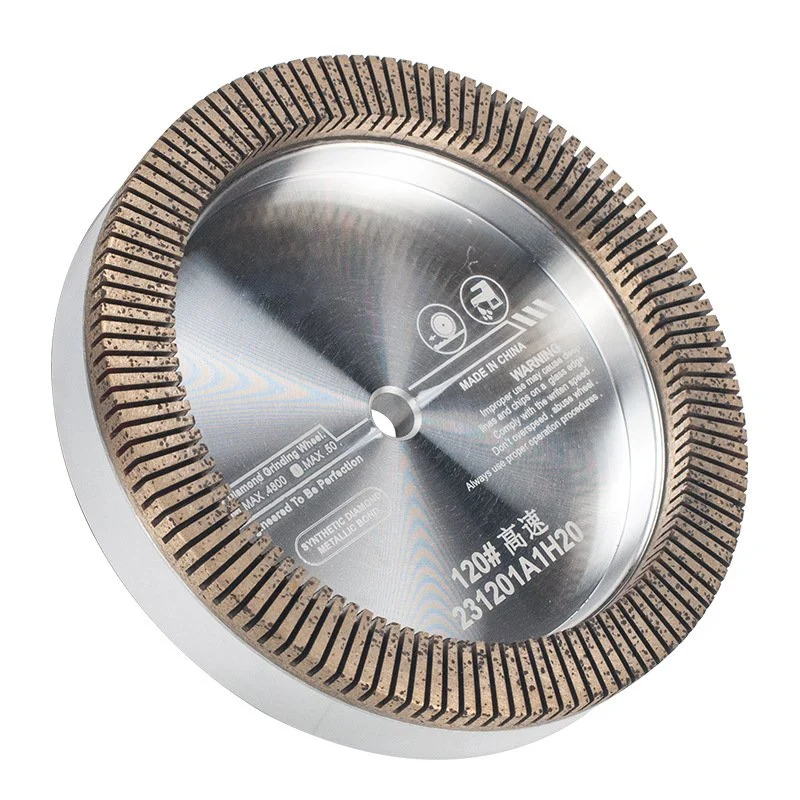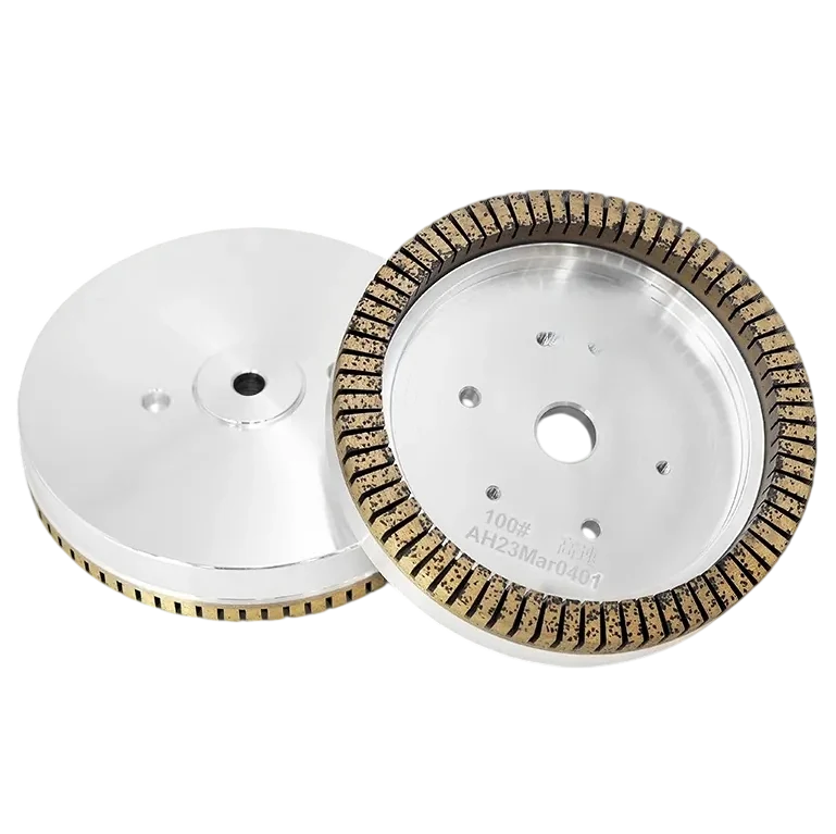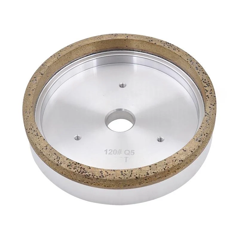
glass double edging wheels · diamond wheel for glass · resin wheel for glass · grinding wheel specification · glass edging machine
Glass Double-Edging Machine Wheels: Specifications, Grinding Ratios and Wheel Angles
A practical guide to common glass double-edging wheel specifications, diamond-to-resin grinding ratios, machine-head sequencing and front-angle or rear-angle adjustment.
A practical guide to common glass double-edging wheel specifications, diamond-to-resin grinding ratios, machine-head sequencing and front-angle or rear-angle adjustment. Start by confirming the machine, wheel position and application before comparing a replacement wheel or requesting a quote.
Quick answer
Glass double-edging machine wheels should be selected by machine head, edge position, wheel profile, glass thickness, removal allowance and finish target. A common wheel specification format is D-H-W×X:
- D = outside diameter
- H = bore
- W = working-layer width
- X = working-layer height
For example, 150-12-15×10 means a 150 mm outside diameter, 12 mm bore, 15 mm working-layer width and 10 mm working-layer height. Always confirm the complete drawing, tolerance and machine fit before ordering.
The usual process moves from removal to finishing: metal-bond diamond wheels for rough and fine grinding, resin-bond diamond wheels for precision grinding, and BK, 10S40 or wool wheels for polishing. The actual sequence and grinding ratio must be tuned to the equipment and glass.
Common specifications for glass double-edging wheels
The following table converts the supplied reference image into HTML so the specifications can be searched, copied and compared. The grit and working-layer descriptions are reference values; the machine drawing and current wheel marking take priority.
| No. | Wheel name | Reference specification | Grit | Working-layer form |
|---|---|---|---|---|
| 1 | Metal-bond diamond double-edging wheel | 150-12-15×10 | 80 / 100 / 120 | Segmented / toothed |
| 2 | Metal-bond diamond double-edging wheel | 150-12-10×10 | 150 / 180 / 230 | Continuous rim |
| 3 | Metal-bond diamond double-edging wheel | 150-12-8×8 | 230 / 240 | Continuous rim |
| 4 | Metal-bond diamond double-edging wheel | 175-12-15×10 | 80 / 100 / 120 | Segmented / toothed |
| 5 | Metal-bond diamond double-edging chamfer wheel | 130-12-8×8 | 230 / 240 | Continuous rim |
| 6 | Resin-bond glass edge wheel | 150-12-15×10 | 180 / 200 / 240 | Continuous rim |
| 7 | Resin-bond glass chamfer wheel | 130-12-15×10 | 240 / 320 | Continuous rim |
| 8 | 10S40 polishing wheel | 150×70×40 | 40 / 60 / 80 / 120 | Polishing layer |
| 9 | 10S40 polishing wheel | 130×60×35 | 40 / 60 / 80 | Polishing layer |
| 10 | X-3000 polishing wheel | 150×70×40 | — | Polishing layer |
| 11 | CE-3 polishing wheel | 150×70×35 | — | Polishing layer |
The table is transcribed from the supplied reference image. Wheel names, symbols, grit options and working-layer forms can differ between manufacturers, so confirm the production drawing and machine position before use.
How to read D-H-W×X dimensions
For common double-edging wheels, the dimension string communicates the main mounting and working-layer data in a compact form:
| Symbol | Meaning | What to check |
|---|---|---|
| D | Outside diameter | Spindle clearance, machine position and replacement envelope |
| H | Bore | Spindle or adapter fit, concentricity and mounting clearance |
| W | Working-layer width | Contact width and edge profile coverage |
| X | Working-layer height | Available abrasive layer and expected replacement life |
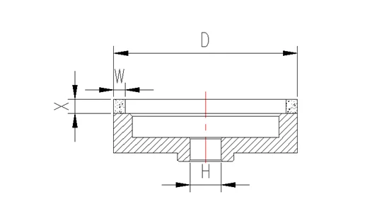
Do not compare outside diameter alone. A wheel with the right diameter but the wrong bore, working-layer width, height or edge profile may not fit the spindle or may shift the glass contact point. When requesting a replacement, send the old wheel photo, marking, machine model and all measured dimensions.
Diamond wheel, resin wheel and polishing-wheel allocation
Glass edge processing is commonly divided into rough grinding, fine grinding, precision grinding and polishing:
- Metal-bond diamond wheels remove most of the allowance during rough and fine grinding. A toothed or segmented working layer can be used as specified by the wheel and machine system.
- Resin-bond diamond wheels take a smaller remaining allowance and refine the edge before polishing. They are not normally a direct substitute for a first-stage heavy-removal wheel.
- BK wheels, 10S40 wheels and wool wheels are used in polishing positions when the line requires the specified visual finish.
The machine-head sequence in the supplied reference is a typical configuration, not a universal rule:
| Head | Reference wheel and operation |
|---|---|
| 1 | Roughing: metal-bond diamond wheel 150-12-15×10-100#, 32 teeth |
| 2 | Fine grinding: metal-bond diamond wheel 150-12-10×8-150# |
| 3 | Fine grinding: metal-bond diamond wheel 150-12-8×8-230# |
| 4 | Chamfer grinding: resin chamfer wheel Ø130×12-10×10-240# |
| 5 | Chamfer polishing wheel |
| 6 | Chamfer grinding: resin chamfer wheel Ø130×12-10×10-240# |
| 7 | Chamfer polishing wheel |
| 8 | Precision edge grinding: resin edge wheel Ø150×12-20×10-200# |
| 9–11 | Polishing wheels |
This order is common for a general glass double-edging line, but different manufacturers and machine models use different head layouts. Match each wheel to its real spindle position, edge profile and polishing target.
Grinding-ratio allocation: a starting reference
The grinding ratio describes how the rough, fine and precision heads share the total material removal. One practical reference allocation is:
- Head 1 roughing wheel: 70%
- Head 2 fine-grinding wheel: 15%
- Head 3 fine-grinding wheel: 10%
- Head 8 precision-grinding wheel: 5%
For a 20-head straight-line double-edging machine processing 10 mm glass at a line speed of 2.3 m/min, the supplied example uses a 2 mm removal allowance on each side:
| Head | Share of single-side removal | Example removal |
|---|---|---|
| 1 | 70% | 1.4 mm |
| 2 | 15% | 0.3 mm |
| 3 | 10% | 0.2 mm |
| 8 | 5% | 0.1 mm |
| Total | 100% | 2.0 mm |
These figures are for process planning, not a fixed production recipe. Adjust the allocation from actual glass thickness, edge profile, wheel wear, motor load, coolant, edge quality, chipping and downstream polishing results. If a later wheel is forced to remove too much material, it may load, burn, chip the edge or wear prematurely.
Front-angle and rear-angle grinding
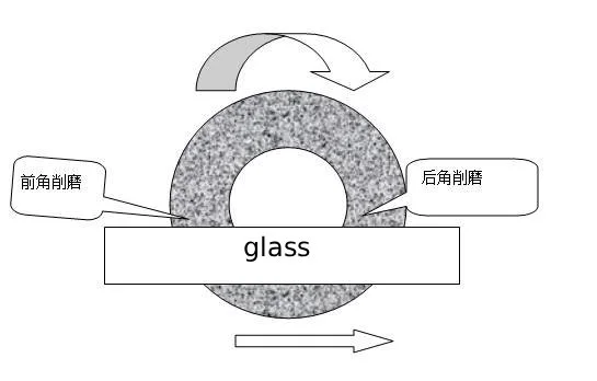
“Front-angle grinding” and “rear-angle grinding” describe the relationship between the wheel working face and the glass edge during contact. The angle is adjusted mainly by changing the tilt of the grinding-head motor during machine setup.
The intended condition is for the wheel’s front and rear angles to participate in grinding as consistently as the machine design allows. If the wheel contacts only one edge, the load becomes concentrated. This can reduce wheel efficiency and contribute to glass edge flaring, chipping, uneven removal or an unstable finish.
Use this adjustment sequence during setup:
- Confirm that the wheel profile and working-layer width match the head position.
- Check spindle runout, wheel seating, holder cleanliness and glass alignment.
- Adjust motor tilt in small increments so the working face contacts the intended front and rear areas.
- Run a controlled sample and inspect both edge sides for flaring, chips, haze, scratches and unequal removal.
- Recheck the angle after wheel dressing, replacement or a change in glass thickness.
What to send for a wheel recommendation
For a reliable replacement or new-wheel recommendation, send:
- Machine manufacturer and model, head number and wheel position
- Glass thickness, type, dimensions and edge profile
- D-H-W×X dimensions, tooth count or continuous-rim requirement
- Current wheel marking, grit, bond and working-layer height
- Line speed, spindle speed, coolant condition and dressing method
- Current grinding ratio or allowance by head, if known
- The problem to solve: chipping, flaring, haze, scratches, loading, low removal, vibration or short wheel life
See the ZHUIFENG diamond wheel range, resin wheel range or contact page for application review and OEM wheel specifications.
Key takeaways
Read a glass double-edging wheel as a complete system, not as a diameter-only product. Use D-H-W×X to communicate the main geometry, use metal-bond diamond wheels for the major rough and fine removal, use resin wheels for controlled precision grinding, and use polishing wheels for the final finish. The 70/15/10/5 grinding allocation and the 2 mm example are useful starting points, but every machine line needs adjustment based on its actual wheel position, glass, angle, coolant and edge result.
Frequently asked questions
How do I read a glass double-edging wheel specification?
A common format is D-H-W×X: outside diameter D, bore H, working-layer width W and working-layer height X. For example, 150-12-15×10 indicates 150 mm outside diameter, 12 mm bore, 15 mm working-layer width and 10 mm working-layer height. Confirm the drawing and tolerance before ordering.
Which wheel is used first on a glass double-edging machine?
Metal-bond diamond wheels are commonly used for rough and fine grinding, resin-bond diamond wheels for precision grinding, and BK, 10S40 or wool wheels for polishing. The exact sequence varies by machine model, edge profile, glass thickness and target finish.
What is a typical grinding-ratio allocation?
One practical reference allocation is 70% for the first roughing wheel, 15% for the second fine-grinding wheel, 10% for the third fine-grinding wheel and 5% for the eighth precision-grinding head. These values are starting references only and must be adjusted from actual edge quality, load, heat and removal results.
Why must both the front and rear grinding angles participate?
The wheel working face should contact the glass consistently through the intended front and rear angles. Adjust the grinding-head motor tilt so the wheel is not cutting only on one edge; an unsuitable angle can contribute to edge flaring, chipping, unstable removal and premature wear.